Borg Warner Actuator Wiring Diagram

Borg Warner 4406 Transfer Case With Images Transfer Case Borg

Ford Cd4e Transmission Solenoid Block Pack New Borg Warner 50082

Details About Dodge 42re 44re 46re 47re 48re Governor Pressure

Set K31 Turbo Charger Hot Brand New Diesel Series 60 12 7l Engine

Borgwarner Efr Installation Guide Turbosource

Details About 01m Transmission Wiring Harness 7 Piece Solenoid Set

Prior to the r 10 r 11 overdrive there was the r 9 overdrive which was a part mechanical part electric overdrive.
Borg warner actuator wiring diagram. This is most appropriate for applications running between 10psi and 20psi of boost. Low boost medium boost and high boost. The diagram below is for those of you who get a. Auburn hills michigan may 21 2020 borgwarner a global leader in clean and efficient technology solutions for combustion hybrid and electric vehicles announced that it is great place to work certified.
Choosing the right actuator is the coarse adjustment and then the fine tuning can be done through a very handy rod swivel joint. Three actuator specifications are offered. Borg warner overdrive tech tips the borg warner overdrive r 10 r 11 electrical overdrive was first introduced in 1940. We hope you ll agree that the efr product line changes this.
It tells you the possible causes when your engine shows failure symptoms. The efr turbo is supplied with a medium boost actuator canister. These were used in studebakers gm and ford cars and trucks. In this discussion all of the information i give you here is for the r 10 r 11 overdrive models.
It gives your truck a semi automatic tranny setup and you will have a 3 4 split shift unit. Please refer to the borgwarner catalog if the low boost or high boost canisters are needed as component replacements.

Borgwarner Efr Turbo Overview Youtube

Borgwarner 177272 S300sx3 Turbocharger 60mm 2 36 Compressor

Details About New Oem Borgwarner S3b Turbocharger Man Truck

Turbocharger For 2007 And Up Deutz Tcd2015 Engine Borg Warner
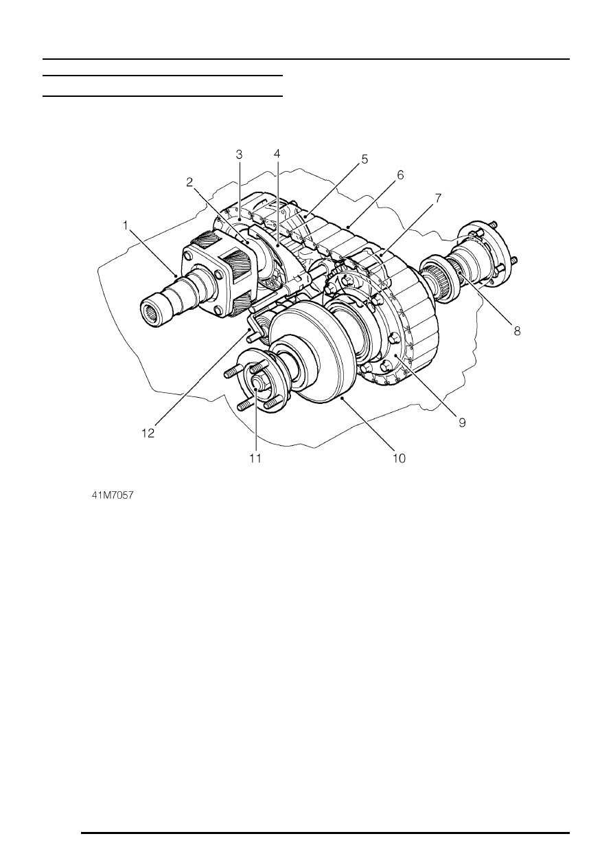
Range Rover Borg Warner 44 62 Transfer Box Manual Part 2

Details About Gm 6t40 6t45 6t50 Gen 1 Sonnax Zip Kit Cruze
Borg Warner Maynards Industries

Transmission Parts Now Superior Ford Ke4od 4r100 Shift
Borgwarner 177248 S400sx3 Turbocharger 71 08mm 2 80 Compressor

Solved Need Wiring Diagram For The Borg Warner 4405 Control Trac

Best Mod For Efr Turbo Youtube

Borgwarner 11589880036 Efr 6258 G Turbocharger B1 Turbo Frame

Borgwarner Turboalimentadores Turbocharger Motor Oil
