Bosch 5 7 Abs Wire Diagram

Diagram Of The Esp Electrohydraulic Modulator Abs Bosch 5 7
Bosch Abs Pump Wiring Diagram Kgv Breitewiese De
Bmw 3 E46 Manual Part 125
Bimmerforums The Ultimate Bmw Forum
If I Remove Abs Fuse Does That Disable The Abs Module Completely

Ecu circuit diagram for bosch ecu schematic 99 00 ecu circuit diagram database consist of 400 documents for downloading.
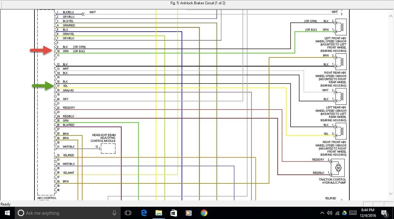
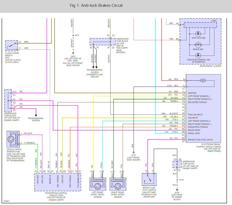
Bosch 5 7 abs wire diagram. Passat abs module removal for repair duration. View and download bosch abs m4 user manual online. Rl wheel speed sensor. C0800 high voltage over 16v o battery voltage wire fuse c0800 low voltage 8v or less o battery voltage wire fuse c0035 wss fl continuity o wss conn wire harness.
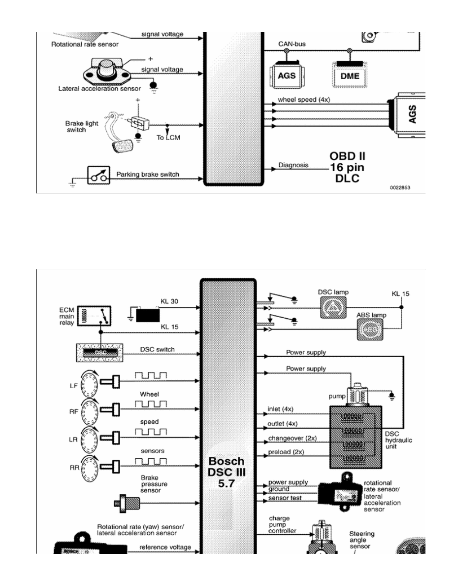
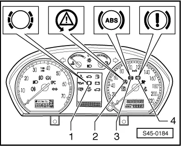
Valve rly 12. Ebd warning lamp. Front right valve in fr. Bl bosch 5 3 abs abscm stop switch ignition switch abs ebd 10a stop lamp has diagnosis.
Ecu wiring diagram schematics for cars and additional information for bosch edc16 edc17 edc15 me71 me75 med7. Valve relay state. Abs troubleshooting for trucks trailers and buses. Ebd lamp 9.
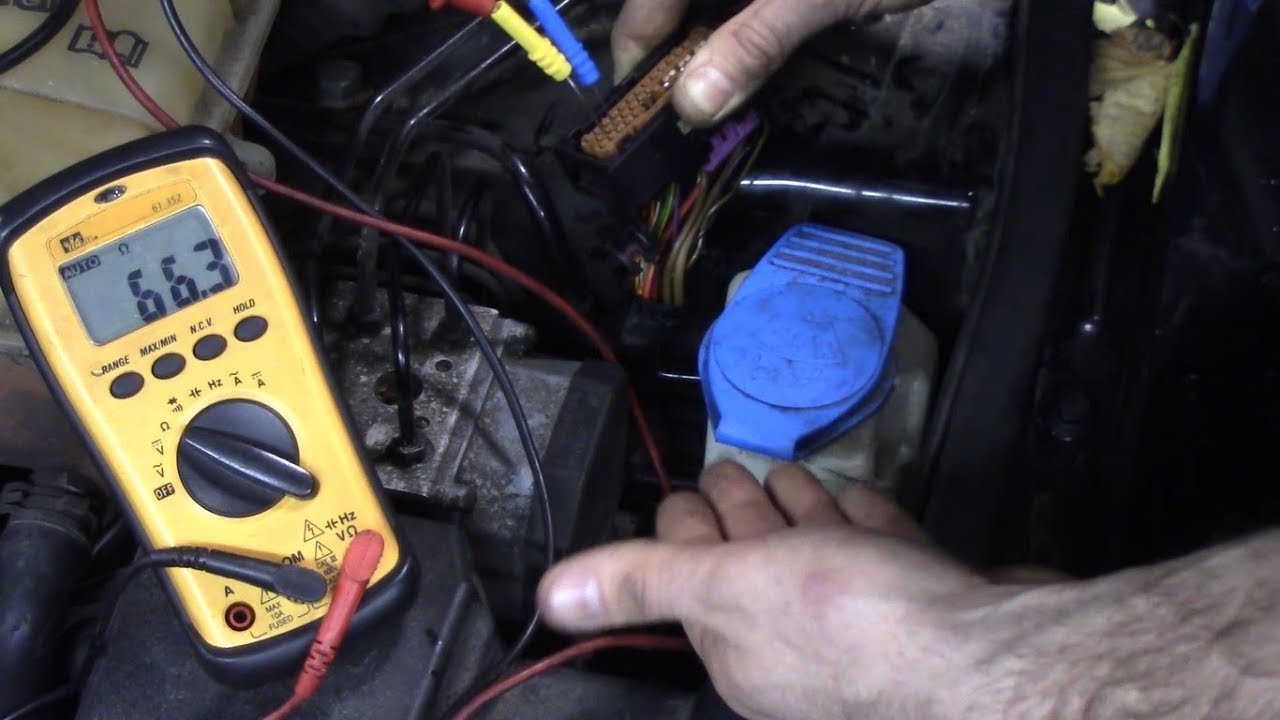
It has a usb connec tion to the laptop and a motorsport connector to interface with the abs m4 wire harness. To help determining whether the 2 wire hall effect abs sensor is functioning correctly different deviations from the example signal are mentioned along with possible causes. The 5 3 is smaller by almost half lighter by 2 1 2 lbs and costs about 60 less than the bosch 5 system. Pump rly 11.
B lamp 10. The signal from the sensor is shown and can be downloaded. Bosch type relay wiring diagrams. Vw abs module repair 3c0 614 109 c trw this video demonstrates how to remove the electronics section of the abs module to solder the components on the pcb.
Bl bosch 5 3 abs abs external wiring diagram. Coding the bosch 5 3 and 5 7 abs modules duration. 17 wiring diagram abs m4 clubsport bosch motorsport abs m4 manual 49 54. Gia omanashvili 57 884 views.
Motor 13. Pump relay state. Abs lamp 8. Bl bosch 5 3 abs system bosch abs.
With a lab scope a 2 wire hall effect abs sensor signal voltage is measured with the wheel turned by hand. Front left valve in fl inlet 14. Rr wheel speed sensor. Thomas exovcds 293 844 views.
Ecu wiring diagrams listed by make and model.
Bimmerforums The Ultimate Bmw Forum

C7af Citroen Berlingo Multispace Wiring Diagram Wiring Resources

Frustrating Rear Abs Problem Fixed New Module Bimmerfest
2002 E39 Asc Brake Abs Lights On Diagnostic Procedure Parts
Abs Module How Can I Get Air Out Of The Abs Module Without Scan
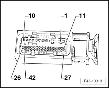
Volkswagen Workshop Manuals Polo Mk4 Brake Systems Abs Adr
Bimmerforums The Ultimate Bmw Forum
Abs Esp Bosch 5 7 Unit Can I Replace Page 3 Audiworld Forums
Skoda Workshop Manuals Fabia Mk1 Chassis Abs Adr Tcs Edl

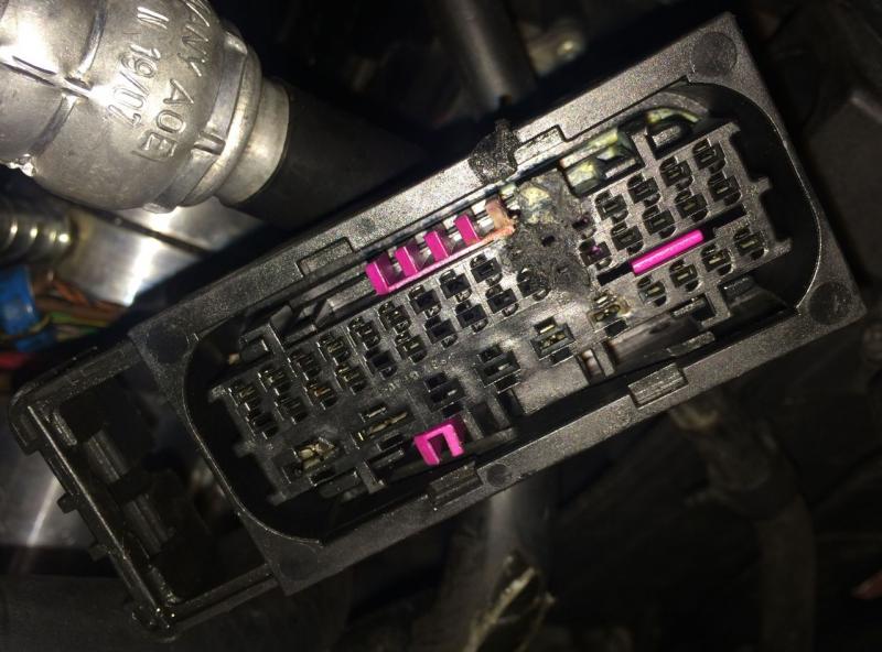
Bosch Dsc 5 7 Abs Module Diagnosis And Repair Bimmerfest Bmw

Service Manual Musso Motor Oil Transmission Mechanics Free
Abs Module No Communication 2001 Vw Passat 1 8t Youtube
Lbc 341x 01 Prosound Cabinet Speakers Pacat Co Uk
